Analog BFO Alignment with a NanoVNA
I’ve been making a lot of progress on my homebrew 20m SSB rig. I got all the parts roughly soldered together on the bench for testing. In order to get any sound out of an SSB receiver using the filter method, you need to align the BFO to the filter passband. So that is what I tackled next.
That may sound like it needs a bench full of test equipment, but in this amazing time we live in, we have tools like the NanoVNA and tinySA at our disposal for next to nothing compared to the cost of a bench full of test equipment in the days of yore.
And, it turns out you can get this job done with surprisingly little — a NanoVNA, a simple attenuator, the product detector, and the audio chain of the receiver itself.
The Setup
My BFO runs at roughly 9 MHz and uses a discrete crystal oscillator that needs to sit at just the right offset from the crystal filter passband. Get it wrong and you’ll hear distorted audio, or worse, suppress the sideband you’re trying to receive. In our case, since this is aimed at the 20m band, we need to do upper sideband (USB). So we need to place the BFO at a frequency just outside the lower passband edge. Note that it matters here that the BFO frequency is below the rig’s main frequency. If it were above, we’d need to do the inverse. It would be the inverse for LSB (e.g. for 40m or 80m bands), as well.
I started with a 9 MHz crystal oscillator. But in order to find out what exact frequency it should run on, I needed to first scope the crystal filter to find the exact passband edges. Once we understand the filter, we can do some simple math to find the place to tune the BFO. This is easily accomplished with a NanoVNA.
But then how to figure out the BFO frequency? The trick is that the product detector and audio amplifier stages were already working, so I had a built-in way to listen to the result in real time.
NanoVNA Filter Sweep
As always, I ensured the NanoVNA was calibrated for the frequency range I was working on.
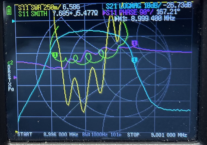
Next, I swept the crystal filter with the NanoVNA to find the passband edges. The filter’s response showed up clearly—a steep-sided passband on 9 MHz. I noted the -3 dB and -20 dB points (relative to center), and the center frequency. In my case the center frequency showed an absolute insertion loss of around -6 dB on the S21 trace, so the -3 dB points (relative to center) appeared at -9 dB absolute, and the -20 dB points at -26 dB absolute. These are the defining points of the passband. The BFO frequency needs to land just outside the lower passband edge for USB reception. According to the literature, it should ideally be around the -20 dB point — on receive this keeps the BFO well clear of the passband, and on transmit the filter’s attenuation at that point provides carrier suppression.
My filter is a commercial off-the-shelf filter and is a little narrower and notably less flat than I would like. I may deal with this at another point, but for now this is what I have. Proceeding with the procedure, the measurements came out as follows:
| Passband Point | Frequency (MHz) |
|---|---|
| Lower -20 dB | 8.99680 |
| Lower -3 dB | 8.99730 |
| Center | 8.99810 |
| Upper -3 dB | 8.99890 |
| Upper -20 dB | 8.99938 |
That results in a -20 dB passband of 2.6 kHz, and a -3 dB passband of 1.6 kHz. There is nothing magic about the center frequency but it helps to locate the correct passband edges. We will use it in a bit for tuning the BFO.

Aligning by Ear
Now that we know what the IF passband looks like, we need to place the BFO so that the center of the desired audio range sits at the center of the passband. We can use the product detector and audio amplifier stages to listen to the result in real time. In my case, given this rig’s topology, this chain looks like:
flowchart LR
    IF["`**_IF_** Input Signal`"]
    RFAmp1["RF Amplifier"]
    CF["`_Crystal Filter_`"]
    RFAmp2["RF Amplifier"]
    Detector["Product Detector"]
    BFO["BFO"]
    Audio["Audio Amplifier"]
    Speaker["Speaker"]

    IF --> RFAmp1
    RFAmp1 --> CF
    CF --> RFAmp2
    BFO --> Detector
    RFAmp2 --> Detector
    Detector --> Audio
    Audio --> Speaker
From here we can use the NanoVNA as a signal generator. In the Stimulus menu there is a “CW Freq” entry that lets you set the frequency of the generated signal. The ideal place to inject it is into the amplifier before the crystal filter, for best tuning of the whole chain.
Because of where it enters the signal chain (where levels would normally be quite low), we need an attenuator before injecting it into the rig to prevent overdriving the amplifiers and the mixer. These can easily be built from a few resistors, a bit of copper clad, and a couple of SMA connectors — I plan to post another article about that. I used a 23 dB attenuator here.
The rest of the explanation uses the numbers from the filter tested above. Your math may be a little different, but the principles are the same.
So which frequency do we dial into the NanoVNA? The filter center frequency is easy to read off the trace: 8.99810 MHz. That is what we inject.
Given that we have such a narrow filter, we want to ensure that we preserve as much of the useful voice range as possible. The minimum cutoff is usually about 300 Hz for SSB, so if we place the BFO such that the lowest audio frequency lands at the bottom of the -3 dB passband, that gives us 1600 Hz of unattenuated audio before we run off the upper edge. Shifting the BFO further down also helps push the carrier further off the passband. Estimating from the filter’s rolloff between the -3 and -20 dB slopes, that gives us about 2.2 kHz of useful bandwidth, spanning roughly 300–2500 Hz of audio.
Now, what tone should we hear when the BFO is correctly placed? The BFO sits 300 Hz below the lower -3 dB edge (8.99730 MHz), putting it at 8.99700 MHz. The audio tone we hear is the difference between the injected signal and the BFO:
8.99810 - 8.99700 = 0.00110 MHz = 1100 Hz
We expect to hear an 1100 Hz tone from the speaker when the BFO is properly tuned.

As you can see, as steep sided as it is, we can’t quite get the BFO down to the ideal -20 dB with my filter.
With the target frequency known, connect the NanoVNA’s output through the RF amplifier before the crystal filter and into the rest of the chain. If everything is close to alignment, some sound comes out of the speaker. It probably won’t — it certainly didn’t for me. In my case, I knew that the center frequency was far enough below the 9 MHz frequency of my BFO crystal that I would need to shift it down a fair bit. The classic literature says to put an inductor in series with the crystal to lower the frequency. Through trial and error, I landed on 10 uH. That got me sound coming out of the speaker. Once you are close enough, you can tune the BFO with the trimmer capacitor you hopefully included in your build! I had 22 pF to adjust with and that was enough.
By adjusting the BFO trimmer capacitor, I could hear the beat note shift in pitch through the speaker as the BFO frequency moved relative to the filter edge. The remaining task was to match it to 1100 Hz. For that, an online tone generator does the trick. I used this one and played it from my phone. If you have the phone near one ear and the other near the speaker, it’s not too difficult to match the beat note to the target audio.
The procedure was straightforward:
- Sweep the filter — characterise the passband with the NanoVNA and note the edges
- Inject a carrier — use the NanoVNA as a signal source at a known frequency within the passband
- Adjust the BFO — turn the trimmer while listening to the audio output
- Match the tone — pull up a tone generator website on your phone and match the beat note to the target audio frequency by ear
- Check the result — The NanoVNA output is considerably stronger than a typical received signal, so even tones near the filter edges should be clearly audible. Tune the NanoVNA down 800 Hz from where you have it and you should hear a 300 Hz tone at the bottom of the usable range. Then tune the NanoVNA up 1900 Hz from where it is now set, and you should hear a 2200 Hz tone near the top of the usable range.
When the BFO is in the right spot, speech sounds natural through the product detector — no chipmunk audio, no muffled lows. You can hear immediately when it’s off. If you are in a place to get it on the air, the ultimate test is if the SSB sounds good. If it does, you’re good to go.
Takeaway
The NanoVNA is far more useful than just an antenna analyser. Paired with a working product detector and audio chain, it gives you everything you need to set a BFO frequency without a signal generator, frequency counter, or oscilloscope. The receiver itself becomes the test instrument.
73 de EI9ITB